
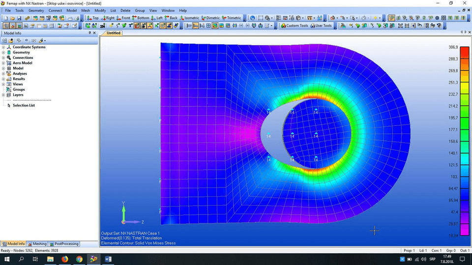
What distance away? and what fudge-factor to use? Well, that has to be developed on prior, more detailed, modeling of similar parts. Often times a fudge-factor on top of the extracted stress value is applied to build in some conservative margin. At a certain distance away from the stress singularity (~1mm in the example plot below), it is assumed the stresses are adequately far away and are thus reported. One first creates a path of stress to the singularity. This is similar to what is sometimes done to estimate stresses for weld fatigue. It serves as a good way to ball park a similar type geometry. This works great if the load pattern and geometry is close to the textbook cases. Roark's formulas for stress and strain is a classic that is often used to determine the appropriate factors relative to the nominal stress. There is still engineering judgement on deciding what radius to use to best reflect the actual part. fillet radius) along with mesh convergence study is the way to go. How does one overcome stress singularities?Ĭreating a submodel at the high stress locations with enough detail (e.g. Constraint Equations, Coupled Nodes etc.a tension bar with one end surface fixed in all direction. sharp corners has theoretically infinite stresses because the radius is zero What are the common causes of stress singularities? Stress singularities are artificial stresses computed because of simplification in the FEA model.